Buid your machine tools

How to make your own machine tools (lathe, milling machine) and improve them according to needs and financial means. These pages are intended to provide methods of design and realization so everyone can adapt these technical capabilities. 
Of course the home made is not limited to lathes and milling machines, it is also possible to make an EDM machine for mechanics, machines for modelers (hot polystyrene cutting, router), well sure there are also 3D printers and some have even tried cutting or laser engraving.

Presentation

My current machine

The construction of machines is fastidious and requires patience and precision. You must begin by knowing what you are able to make with the material you have, there is no place for improvisation and it is better to build simple at begining then to improve what you have made. Never forget that once you finish your first machine, even if it seems a little simplistic, you now have to do better.
Here is the machine with which I am currently working, its realization is entirely personal, all metal. The engine is provided by a Peugeot engine block equipped with a two speeds gear box and an electronic variator. The chuck is purchased.

The construction of this machine is quite difficult but was very instructive, if it was to redo I will change some points to simplify.

Stepper motors allow the numerical control  of the 3 axis while keeping cranks for simple operations.

Brief history

At the risk of making purists startle, my first lathe was a manual drill mounted on a wooden frame in front of crossed carriages made of aluminum profiles. This does not seem very mechanical, but it is the starting point of a generation of three machines. So, tell yourself that nothing is impossible for a stubborn modeler.
The drill is a good start solution because any good handyman has one and so you have a motor, a chuck and even a speed variator. If you can, prefer a model without hammer because the axial backlash of the spindle is much less.
The results obtained with this tour surprised me so much (0.05mm diameters accuracy) that I decided to do better and especially stronger. 
 
From this observation was born the idea of ​​my second machine (stub lathe): 
The idea of the drill and the wooden base are preserved, however everything is changed at the level of the crossed carriages. The slides are made of steel "stub" which is sold already grinded and calibrated, it remains only to cut to length. Each carriage and the two slide supports are drilled together on a drill press paying particular attention to the parallelism of the two holes. Provide adjustment screws for the backlash. 
 
As for the displacement screws, the diameter M6 is essential because the pitch of 1mm is very useful.
The geometry is checked by machining a cylinder and then measuring the taper with a micrometric caliper, for the adjustments it is enough to trim the back of the drill and to twist it with the help of the lateral screws of the rear part of the frame ( see general picture). Do not expect miracles for long pieces, but for small steam engines this is enough. 
 
This second lathe allowed me to build the one I am currently using, including the bearing housings and the two-speed gearbox that make up the spindle this with the help of a special plate for larger parts (in french). 
 
So, convinced? 
For those who already want to embark on the adventure you can download the plans of my second machine. These are scanned plans that everyone can adapt according to the equipment they have.
See more
Cnc3Axes
3 axis CNC machine control software. Freeware for download on this site.
European Model Engineering
Site in which you will find plans for the realization of machines and tools, in particular a metal lathe.
EDM
Everything to build a pulsed current EDM machine. The site offers two books very well done on the subject.
Download
Stub lathe plans
Plans of my second tour in PDF format.
See more
Cnc3Axes
CNC controller software
European Model Engineering
Machine tools plans
EDM
All to build your own machine
Download
Stub lathe plans
my second lathe

Design

Before you start: the basics

A good metal machining machine must be rigid, you will reduce deformations and vibrations which improves accuracy and cutting performance. 
 
The technical choices will be adapted according to your specifications and of course your finances. If you think like me to turn your machine into CNC, it will be designed from the beginning to avoid unpleasant surprises. 
 
First and foremost, the right questions must be asked to establish a set of specifications: 
What do I want to machine ? 
What size do I need ? 
Do I need a lathe, a milling machine or both ? 
What level of performance do I need ? Speed, power, accuracy, etc ... 
What will be the rate of use ? This will evaluate the service life. 
What is my level of equipment for the conctruction ? 

Guideways

patin
Guideway and bearing block
douille
Linear ball bearing
écrou bille
Ball screw nut
One of the most important technical choices is the technology of axis guideways and their motion. 
 
Prismatic metal on metal guideway, linear ball bearings, preload bearing blocks? 
 
Iso screw drive, trapezoidal screw, ball screw? 
 
For each choice, the quality and the result will be different but the price too, hence the difficulty of choice. 
For example a 15mm bearing block costs alone about €30 (2018), and normally it takes 4 per axis, or already more than €350 for 3 axes.
For my machine I made the choice of 100% home made which imposes virtually metal-on-metal guides and iso screws for motion. 
This choice is the most economical and has a very good rigidity when everything is very well adjusted. This guidance technology is the one used on old industrial machines. 
Of course, today's CNCs use almost all preload roller blocks and guideways as well as preload nut ball screws, but it is out of reach of the hobbyist coin carrier.
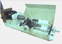
With metal / metal slides, provide for long guide lengths, in practice respect a length / width ratio greater than 1.5. For the carriage of the column described the ratio is 2 (width = 60mm, length = 120mm). This rule avoids the phenomenon of jamming and decreases the defect of "lace" of the carriages, thus better precision of the guides. 
 
All carriages must be fitted with brass, bronze or PTFE (Teflon) plates to facilitate sliding. Some plates are equipped with adjustment screws to set up the backlash due to wear. 
 
The feed screws must be chosen with a judicious pitch, the ideal is to use threaded rods M6 because the pitch is 1mm, so with one crank turn, your carriage moves 1mm, add a graduated drum 40 divisions (easy to do with the help of a small spare gear) and you have a 0.025mm caliper.

My lathe spindle

My spindle is driven by a Peugeot drill engine block with two speeds gear box and an electronic dimmer. 
In order to have a better speed range and a good torque to the chuck, I added two other mechanical speeds and a toothed belt reduction, this gives a speed range of 120 to 4500rpm and allows me to take chip depth of more than 1mm in steel with a carbide tool. 
 
The schematic diagram shows the kinematic chain of the spindle and the bearing assemblies.

Drawing the plans

In order to be sure of the result, it is imperative to make serious plans before starting construction, whether these plans are drawn by hand or in CAD no matter, it is a matter of pratice. 
The plans of my machine are now very old and as they were traced by hand on large tracing paper, it is difficult for me to scan and diffuse them. 
That being the case, I started to modelise everything with 3D CAD, and as soon as they are finished I will put a STEP and a native format for download. 
If you do not have professional CAD tools like Solid Works or AutoCAD, there are free alternatives such as DrafSight (2D AutoCAD compliant) or FreeCAD (Solid 3D), the links are in the "see more" section.
See more
CNC Loisirs
French site on the hobbyist CNC home made, you will find everything you need to design and build a machine.
3D CAD FreeCAD
Free and open source software developed by a team of enthusiasts, it is not yet at the level of SolidWorks but is approaching from year to year.
2D CAD DraftSight
Free software compatible with AutoCAD distributed  by Dassault Systèmes, you just have to register.
Download
Stub lathe plans
Plans of my second tour in PDF format.
See more
CNC Loisirs
French DIY cnc machines
FreeCAD
3D CAD freeware open source
DraftSight
2D CAD AutoCAD compliant
Download
Stub lathe plans
my second lathe

Construction

Milling column

The design follows the previous rules. Everything is made from commercial stretched, A60 steel and brass. Its attachment to the back of the frame lathe was planned during the construction of it.
ALL ASSEMBLIES MUST BE PINNED, this ensures good repositioning during disassembly and avoids any movement of the parts, if necessary an epoxy bonding (Araldite) can perfect the whole. All mounting holes must be drill together for perfect alignment.
The carriage consists of an assembly of plates, all assembled by screws CHc and pinned. The first picture shows one side assembled and the other one still disassembled, you can notice the sliding plates in brass (make grooves to facilitate the lubrication).
The pictures show the parts then the assembled assembly and provided with the nut of advance (nut). The assembly of the guides must be done with the carriage positioned on the slide, so no adjustment problem, the pinning will be made after verification of all.
The screw is mounted on a bearing so that there is no backlash, the nut is in brass to limit friction (I consider PTFE but I have not tested). The crank is equipped with a graduated drum. This realization requires a turn, but if it is your first machine, you can do a much simpler editing with conventional nuts and no bearings (see my first machine tool), as soon as your turn is on, no problem to rework.

The milling spindle and its support

In the construction of any machine tool, the spindle is one of the most delicate points. If you already have a lathe, it is imperative to make a serious assembly with bearings mounted with a slight preload (assembly below and plan). If you do not have a machine, you have to brainstorm to use what you can find: small saw spindle (see DIY stores), drill, bike wheel hub etc ... All that is mounted on ball bearings without much backlash can be use. All ideas are good to take and feel free to share yours to improve these pages.
As mentioned above, if you build your first lathe (and you do not have that of a friend) the best spindle is that of a drill without hammer, you will have in addition the motor and the variator. 
The spindle support consists of an assembly of steel plates. The whole is screwed, pinned and glued with epoxy, it's all simply unbreakable.
This support is ready to receive the spindle then to be fixed on the carriage. All the geometry must be adjusted with a comparator using the various carriages to ensure the movements and measure on a square.
See more
CNC Loisirs
French site on the hobbyist CNC home made, you will find everything you need to design and build a machine.
Download
Stub lathe plans
Plans of my second tour in PDF format.
See more
CNC Loisirs
French DIY cnc machines
Download
Stub lathe plans
my second lathe

Numerization

The prototype

What model owner of a machine tool has never dreamed of switching to numerical control (CN for intimates). In fact, some surfing on the web shows that we are quite numerous to have this idea behind the head and even for some already in the workshop. 
 
You guessed it, I took the step and I offer some pictures of the prototype.
An overview of the machine for which only three stepper motors have been added while carefully preserving the original cranks. For me it is important to continue to work with manual control because it is absurd to think that all the parts justify to write a program. The machine is controlled by a PC from parallel port and a few electronic boards.
The mechanics remain very simple, for each axis a stepper motor is added between the screw and the crank. The assembly of the crank necessitated the modification of the rear of the steppers. The motors are attached to the screws with a flexible coupling to overcome the misalignment, against this coupling must be very rigid in torsion to not affect the accuracy.
The motors are 200 steps per turn drived in half-step which gives 400 steps per turn, with a screw pitch of 1mm each step gives an advance of 0.0025mm which allows a great smooth of movements and a very good accuracy (of the order of 0.01mm). The maximum feedrate is 200mm/min which is more than enough for our small machines.
The picture below shows the pre-wiring of the electronics from left to right: the interface boards with the PC, the power supply, the transformers, the three driver boards. 
 
The function of the interface boards is to use the signals from the parallel port, to manage the feedrate (programmable timer), to manage the end stops. Eventually I want to add a hand panel to facilitate manual controls during settings. 
Power is still common to all drivers, but experience shows that with a separate power supply for each axis, the performance is better. 
 
The stepper driver boards are based on the classic L297 and L298 which are easy to find components and offer a good price / performance ratio.
The last part of the puzzle is of course the control software. There are a number on the Internet, the CNC Loisirs site is a great help. Many of these softwares are originally developped for routers 2D 1/2, however Ninos has caught my attention because for an affordable price it seems to offer many possibilities (I have not tested it on a machine). 
 
As much for need as for pleasure, I chose to develop my own software named CncAxes, originally I foresaw only personal use, but in the end I understood that it would be a good idea  to do enjoy everyone, so it is provide as freeware. 

Futur developments

The evolution of computers and operating systems is increasingly limiting the use of the parallel port for our hobbies applications. Recent computers no longer have this printer port and systems from Windows 7 restrict direct access. Software like Cnc3Axes is therefore destined to disappear in favor of more advanced systems connected by USB or Ethernet. 
 
I explored various hypotheses to evolve my electronics / software by testing boards like IPL5X or GRBL on Arduino, but none met my expectations. 
 
To date, in 2018, the best-performing freeware management solution runs Linux with LinuxCNC, either on an old PC that still has a parallel port, or by adding specialized boards (MESA), or by using a Linux system embedded on a Rapsberry or Beaglebone single board computers. It is this last hypothesis that I chose for my future standalone CNC console with a Beaglebone Black board connected to a interface board and a 12 '' touch screen. 
This project is in progress and is the subject of a specific page on this site
See more
Cnc3Axes
3 axis CNC machine control software. Freeware for download on this site.
Linux CNC
Fully customizable, free and open source machine control environment on Linux. 
The top of hobby CNC control.
MachineKit
Based on LinuxCNC, Machinekit uses the same base but is adapted to ARM board systems such as the Beaglebone.
LinuxCNC Console
Design and build of a standalone control panel with touch screen and Beaglebone Black single board computer, runs with LinuxCNC.
See more
Cnc3Axes
CNC control software
Linux CNC
CNC customizable controller
MachineKit
Like LinuxCNC for embedded
LinuxCNC console
Standalone CNC controller
Made with OpenElement
Date mise à jour  
CARNETS JL-S
Technical hobbies
Carnets JLS
Top page